9. Floors and Floor Plans
Floors represent the physical levels of a facility. Each floor can have an uploaded floor plan image, a set of drawn area polygons (wards, wings, corridors), and a collection of units assigned to it. Floor plans are used on the dashboard to show compliance results on top of the actual building layout.
To open the Floors list for a facility, go to Account |
Facilities / Floors / Units, select a facility, and choose
Floors from the action menu.
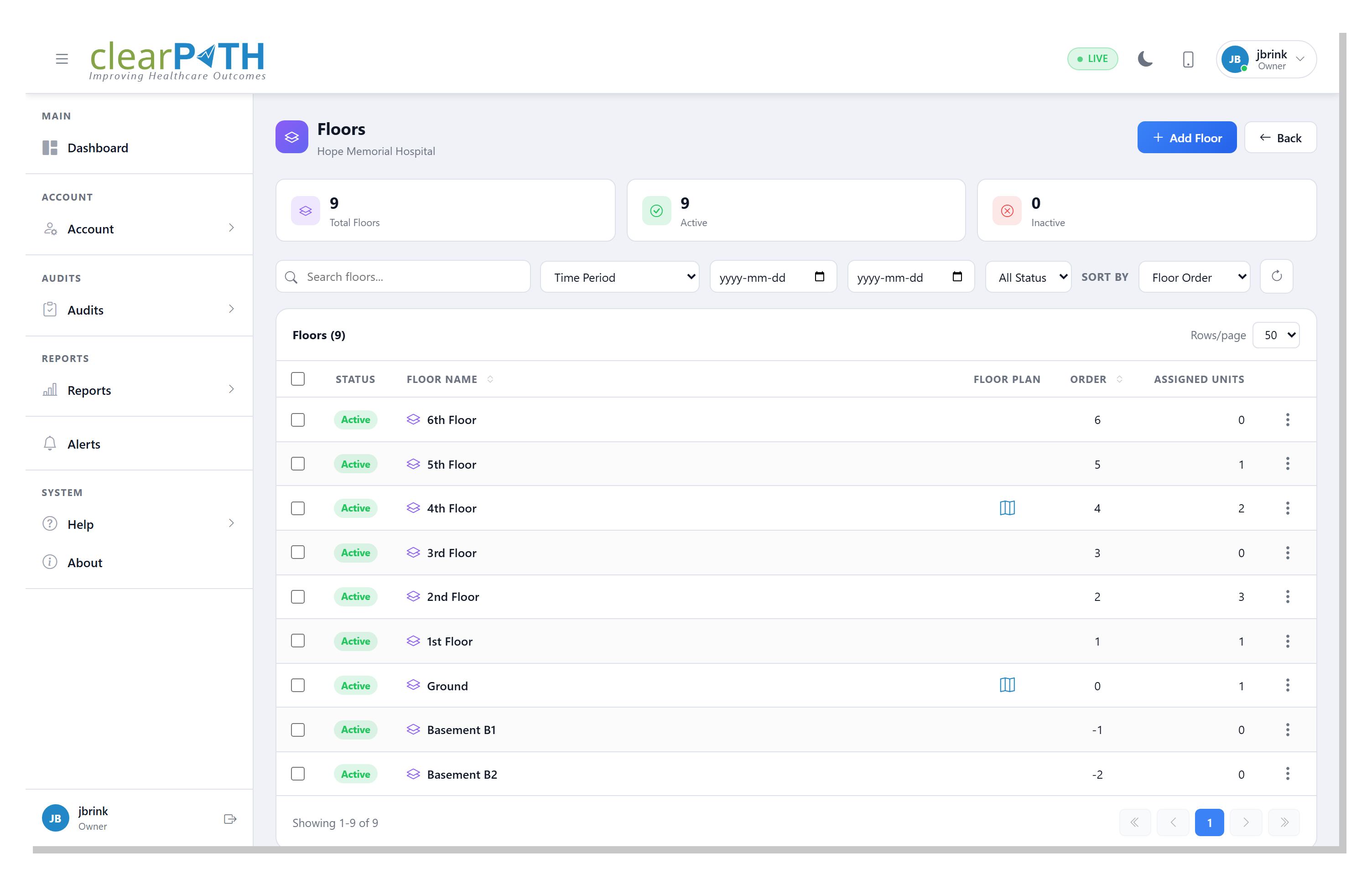
9.1. Floor List
The list toolbar provides:
Search — filter floors by name.
Time Period, Start Date, End Date — scope floor-level compliance statistics to a date range.
Status — show active, inactive, or all floors.
Sort By — order floors by floor order (default) or alphabetically.
Each row shows the floor name, whether a floor plan image has been uploaded, the sort order, and the number of units assigned to the floor.
9.2. Floor Detail
Click a floor to open the detail editor, which is organized into three tabs.
9.2.1. General
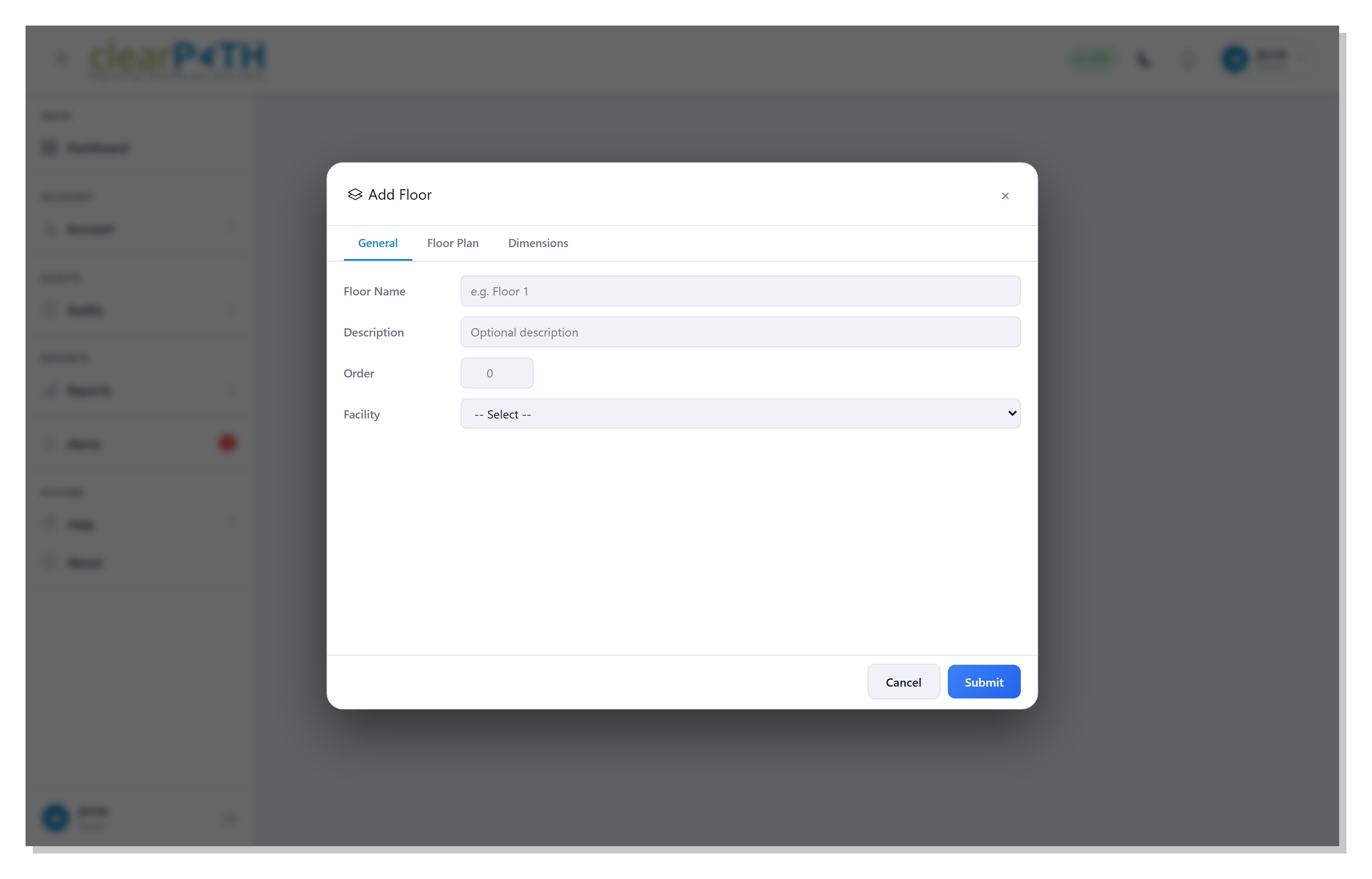
Floor Name— label for the floor (for example,Floor 1orEmergency).Description— optional free-text description.Order— numeric sort order, used to list floors from lowest to highest.Facility— the facility this floor belongs to (read-only).
9.2.2. Floor Plan
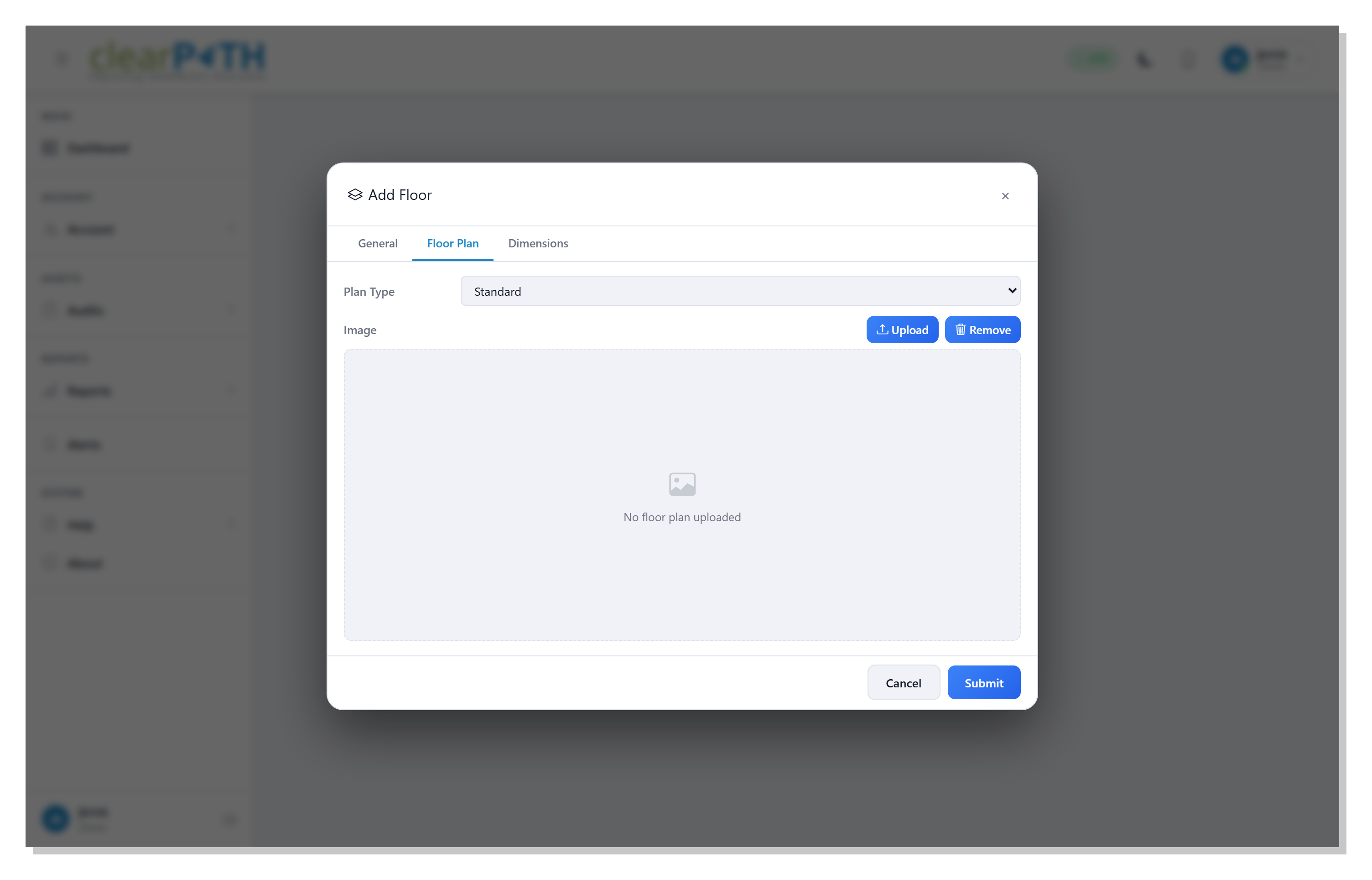
Plan Type—Standardfor a stock layout orCustomfor an uploaded image.Image— upload the floor plan image (PNG or JPEG). UseRemoveto clear an existing image.
9.2.3. Dimensions
Size (W, H)— the width and height of the floor plan image in pixels.Scale— real-world units per pixel. This is set interactively on the Floor Plan viewer using theSet Scaletool.DPI— image DPI, used for printing.Bin Size— granularity used when aggregating observations onto the floor plan.
9.3. Floor Plan Viewer
The Floor Plan viewer opens from the floor’s action menu. It shows the uploaded floor plan with compliance data overlaid by area.
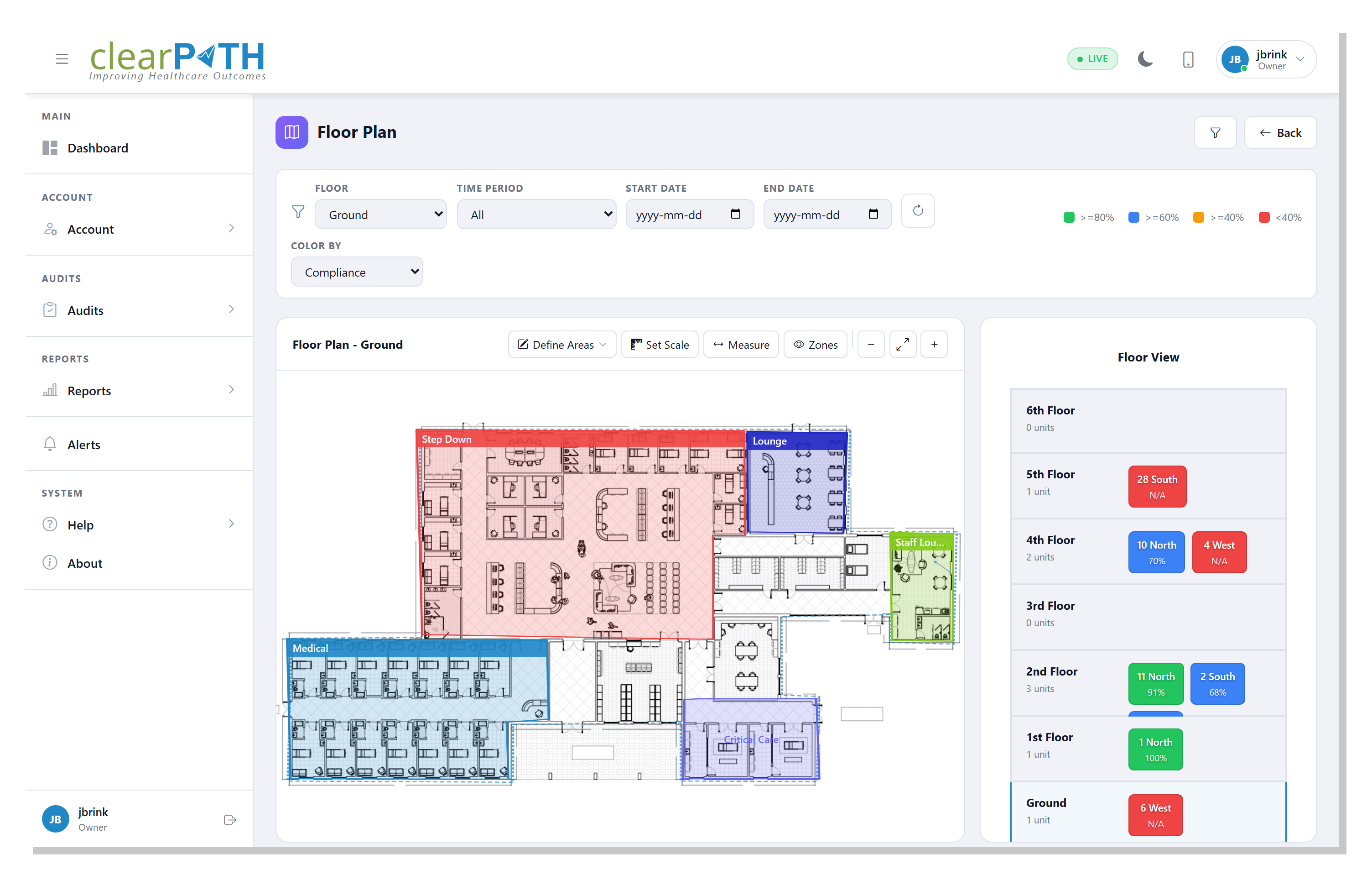
9.3.1. Filters
The filter bar at the top of the viewer controls the data overlaid on the floor plan:
Floor — switch between floors in the facility.
Time Period, Start Date, End Date — scope results to a date range using the same options as the dashboard.
Click the funnel button to show or hide the filter bar.
9.3.2. Drawing Areas
Areas (wards, wings, patient rooms) are drawn as polygons on top of the floor plan.
Click
Draw Polygon.Click on the floor plan to place each polygon vertex.
Double-click to close the polygon and name the area.
Each area is listed in the legend on the floor plan and in the unit panel to the right. The color of each polygon reflects the compliance result for the time period selected in the filter bar.
9.3.3. Setting the Scale
To make the floor plan measurable in real-world units:
Click
Set Scale.Click two points on the floor plan that you know the real-world distance between.
Enter the distance.
Once set, the Measure tool can be used to check distances directly on
the floor plan.
9.3.4. Assigning Units
The unit panel on the right lists all units assigned to the facility. Each unit can be linked to an area on the floor plan so that observations recorded for the unit appear in the correct location.